Pressure-controlled voidless PEEK printing
How we solved the biggest challenge of 3D Printing PEEK Polymers
High-performance polymers
are difficult to print
High-performance polymers such as PEEK are difficult to print; it is hard to ensure that the properties of printed parts approach those of bulk material. Dutch start-up Bond High Performance 3D Technology, however, has succeeded in developing a unique 3D-printing technology – including system mechatronics, software, slicing technology and process validation – for producing high-end functional parts from PEEK. A recent investment by UK-based Victrex, a leading manufacturer of PEEK, is now helping Bond 3D to bring its technology to the market. Among other things, one of the key elements of Bond 3D’s technology, ‘bondability’, is facilitated by pressure-controlled voidless printing.
PEEK, polyetheretherketone, the best-known member of the PAEK (polyaryletherketone) family of highperformance thermoplastic polymers, finds applications in high-end markets such as semiconductor, medical, aerospace, energy and automotive because of its combination of qualities: lightweight, high strength, chemical resistivity, thermal stability (–50 to +150 °C) and biocompatibility.
Printing challenge
Exploiting the design freedom of 3D printing can further increase the application scope of PEEK, on the condition that the favourable properties of bulk material (certified for markets such as aerospace) are preserved in the 3D-printed parts. That they should do so is not self-evident, as standard 3D-printing using FDM (fused deposition modelling) results in a lower density of the material, as compared to bulk material.
This has to do with the transverse orientation of subsequent layers, each composed of small parallel strands, as ejected by the print nozzle. This transverse lattice-like structure achieves adequate strength in the (horizontal) xy-plane, but has a relatively small contact surface between the neighbouring layers; see Figure 1. The resulting products are anisotropic in their mechanical properties.


Transverse orientation of neighbouring layers of printed material for adequate strength in the (horizontal) xy-plane leads to a relatively small contact surface (indicated by the yellow areas on the right), resulting in a reduced strength in the (vertical) z-direction.
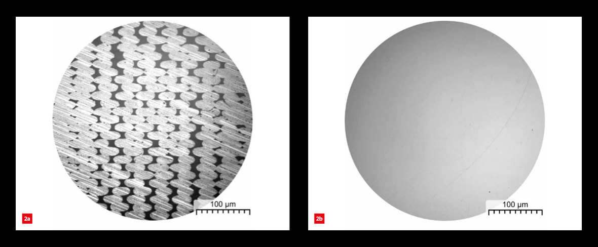
As a result, when compared to bulk material, conventionally printed PEEK products have a drastically reduced strength in the (vertical) z-direction and their density is only some 85 per cent. Figure 2 shows the cross-section of a printed product produced by either standard FDM technology or Bond 3D’s technology (as explained below), the latter showing a virtually voidless result (density > 99 per cent). This is not only relevant for the mechanical strength of products, but also for their liquid and gas transport properties. For example, manifolds can benefit from 3D printing because of the design freedom it offers, allowing for efficient and complex solutions, but these have to be absolutely leak tight.
Therefore, Bond 3D’s challenge was to develop a printing technology for the voidless printing of isotropic products that retain the bulk properties of their base materials. Adding to the equation, PEEK is difficult to print because of its high viscosity in the molten state and its semi-crystalline nature; upon solidification, part of the material will recrystallise, leading to shrink, which will affect the mechanical properties (due to build-up of internal stresses) and dimensional accuracy of the printed products.

Cross-section of a printed PEEK product, showing the printed strands coming out of the plane.
(a) Regular FDM technology.
(b) Bond 3D technology.
Pressure control
The Bond 3D printing technology is an extrusion process. Bulk material is fed to the print head where it is heated to around 400 °C, upon which the molten material is pushed through the print nozzle and deposited on the print table, then subsequently onto the previously deposited layers.
The conventional extrusion process proceeds in a flow-controlled manner: material is fed at a rate that is proportional to the distance the nozzle travels. Inevitably, there are errors. For example, variations in the filament diameter and fluctuations in the temperature of the compressible molten material will affect the flow rate of the highly viscous material through the nozzle. As a result, perfect extrusion cannot be achieved; either more or less material than required will be deposited and the distance between the print nozzle and the top layer of the print will vary. This may lead to an inhomogeneous distribution of the printed material, by either under- or overextrusion (Figure 3). In the latter case, the moving print head causes a kind of bow wave and ‘ploughs’ through the deposited, solidifying material (solidification only takes seconds, so interaction forces will be high).
Overextrusion results in the accumulation of residual material at the side of the nozzle, which will quickly degrade under the influence of the hot print head, as polymers can only withstand temperatures beyond their melting point for a short time. The degraded material might flake off in black specks and contaminate the printed product, deteriorating its aesthetic and mechanical properties. Moreover, the increasing forces between the ‘ploughing’ head and the product being printed may eventually lead to the print being ripped off the build plate. The properties of the build plate (for example steel) are chosen as a compromise regarding the adhesion force with the printing material; i.e., high enough to hold the print, but low enough to facilitate removal of the finished product from the build table.

Flow of the molten polymer (yellow) out of the nozzle of the print head (green) under flow control, resulting in a potentially inhomogeneous distribution of the material. The direction of the moving print head is perpendicular to the plane of the drawing.
(a) Underextrusion.
(b) Perfect extrusion.
(c) Overextrusion.

Flow of the molten polymer out of the nozzle of the print head under pressure control, as developed by Bond 3D, resulting in a homogeneous distribution of material regardless of the width of the gap that has to be filled.
(a) Small gap.
(b) Moderate gap.
(c) Large gap
As overextrusion can end disastrously, underextrusion is generally preferred and the process control is set accordingly. This, however, creates voids in the printed product (Figure 3a). Bond 3D’s solution is pressurecontrolled printing (Figure 4), where the molten material flows to completely fill the gap between previously printed lines; material flow continues until the pressure in the ‘melt pool’ below the print nozzle starts to exceed the setpoint, indicating that no more material can be added. Then the gap has been filled and adjoining lines have bonded completely – this is what Bond 3D calls ‘bondability’ from where the company derives its name.
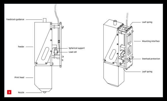
The pressure can be derived from the upward force exerted on the print nozzle at the bottom of the print head by the printed material in the melt pool below. As a first implementation, this force was derived from the motor current required for driving the extruder that delivers print material to the nozzle. This motor current, however, provides a rather noisy signal, so filtering is required, which makes feedback control slow. As an accurate highbandwidth control alternative, Bond 3D designed a flexurebased, friction- and hysteresis-free mounting of the print head on the gantry to which sensitive force sensors are attached; Figure 5 shows a schematic design.
The pressure can be derived from the upward force exerted on the print nozzle at the bottom of the print head by the printed material in the melt pool below. As a first implementation, this force was derived from the motor current required for driving the extruder that delivers print material to the nozzle. This motor current, however, provides a rather noisy signal, so filtering is required, which makes feedback control slow. As an accurate highbandwidth control alternative, Bond 3D designed a flexurebased, friction- and hysteresis-free mounting of the print head on the gantry to which sensitive force sensors are attached; Figure 5 shows a schematic design.

Schematic design of the flexure-based mounting of the print head.
Slicer
In practice, Bond 3D applies a mix of flow and pressure control. Metaphorically this can be compared to the use of an electrical power supply: either setting the current, which yields a certain voltage, or setting the voltage to generate a certain current. Contour lines of shapes to be printed can simply be created using flow control. Here, pressure control does not make sense, as there is no line yet to which the new line has to be seamlessly matched; it’s only in the next step that the gap in between is filled up using pressure control. In 3D printing, the patterns to be printed are generated from a 3D model by a so-called slicer; it partitions the model into layers, or slices, that are to be printed one on top of another. Each layer is a set of 2D shapes, and the slicer determines the paths that need to be printed (similar to the ‘tool path’ for other CNC machines) and the amount of material to be extruded. When pressure-controlled printing is used, the slicer does not need to dictate how much material has to be extruded, but rather to which pressure the extruder has to be driven.
Commercially available slicers cannot distinguish between flow and pressure control, so Bond 3D decided to develop its own slicer that adds information to the slicing profile, indicating whether flow or pressure control is appropriate for the printing step at hand. The additional advantage of a proprietary slicer is that it greatly increases the flexibility in process development; new slicer options can be added almost instantaneously, further improving the quality of the printed products.
Mechanical properties
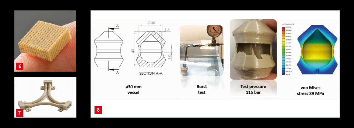
Bond 3D printing technology can produce both highly detailed, accurate porous structures (Figure 6) and voidless products. Resolution is below 0.3 mm and mechanical properties are excellent. Measurements on printed tensile specimens revealed a yield strength of 99 MPa, which compares favourably to the 98 MPa guaranteed by Victrex for its bulk material and exceeds the yield strength of flowcontrolled printed specimens by more than a factor of two.
A gas pressure test on a printed manifold-like part with 1.3 mm wall thickness (Figure 7) showed no failure up to 100 bar; the leak rate was below the detection limit of 3·10-6 mbar·l/s. Another part, a vessel designed to have a well-defined stress concentration at the location with least wall thickness (1.4 mm), withstood up to up 115 bar pressure before bursting, equivalent to a Von Mises stress of 89 MPa in the outer wall (Figure 8). The challenge now is to prove that the fatigue strength of printed parts is on par with that of bulk products. For this, voidless printing is crucial, because even the smallest voids can generate micro-cracks that propagate through the part, eventually leading to fatigue failure. Micro CT scans are used to prove the absence of voids.

Conclusion
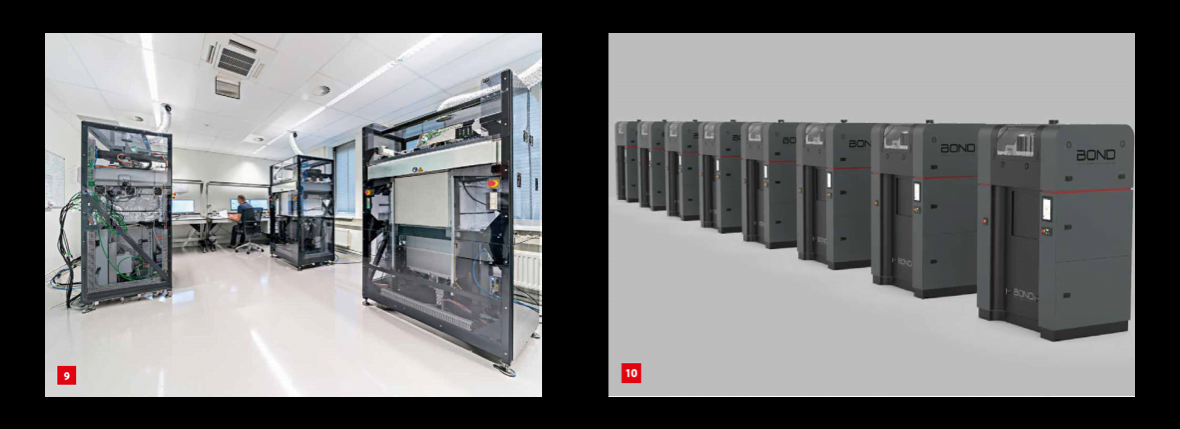
Voidless printing is one of the key performance indicators in Bond 3D’s technology roadmap. Current development at Bond 3D is performed using three functional model printers (Figure 9). A first batch of eight production-ready printers is scheduled (Figure 10) for this autumn. Bond 3D’s patented technology is capable of printing complex, functional parts made of PEEK with excellent mechanical properties, including in the z-direction. This enables the additive manufacturing of high-strength, isotropic parts with properties comparable to those of conventionally moulded or machined PEEK parts, while allowing for freedom in design and complex structures that are not possible using conventional techniques.


