PRESERVING PRECISION
IN PEEK PRINTING
Authors’ Note
Nienke Koopmans and Thijs Tromper (simulation software engineers), Godfried Mensink (team lead/project manager) and Arry Wegdam (operational manager) all work at Bond High Performance 3D Technology (Bond3D) in Enschede (NL).
Article is published in DSPE Mikroniek – nr. 4 2023
Bond3D’s unique 3D-printing technology has vastly expanded the application scope of PEEK. High-strength, isotropic parts can be produced from this high-performance polymer in a pressure-controlled, voidless printing process. Due to PEEK’s high
melt temperature and high coefficient of thermal expansion, thermal effects play
a significant role. Therefore, to ensure the dimensional accuracy of the printed parts, Bond3D has developed an advanced shrink-compensation procedure. The achievable accuracy conforms to the ISO 2768 standard for machining tolerances.
PEEK, polyetheretherketone, is a high-performance thermo- plastic polymer applied in high-end markets such as semi- conductor, medical, aerospace, energy and automotive because of its combination of qualities: lightweight, high strength, chemically resistant, thermally stable (–50 to +150 °C) and biocompatible.
Bond3D has further increased the application scope of PEEK by exploiting the design freedom of 3D printing using its unique technology for producing high-end functional parts from PEEK. This was quite a challenge, as PEEK belongs to the class of high-performance polymers that are notoriously difficult to print, due to their high viscosity and semi-crystalline nature.
Moreover, standard 3D printing using FDM (fused deposition modelling) results in parts with anisotropic mechanical properties and a lower density compared to bulk material. This is related to the transverse orientation of the subsequently printed layers, where each is composed of small parallel strands (‘lines’), as ejected by the FDM print nozzle. This transverse lattice-like structure achieves adequate strength in the (horizontal) xy-plane, but has a relatively small contact surface between the neighbouring layers, which creates voids in the product and leads to a lower strength in the z-direction (Figure 1).

Figure 1: The transverse lattice-like structure created by standard 3D printing exhibits a relatively small contact surface between neighbouring layers. This leads to voids in the product as shown by the cross-section of a printed product (middle) and the exploded view on the right.
Voidless printing
Thus, Bond3D has developed a printing technology for the voidless printing of isotropic products that retains the bulk properties of the base material. It involves an extrusion process in which the bulk material is fed into a print head heated to above the PEEK melt temperature of 343 °C. The molten material is pushed through a nozzle and deposited first onto a build plate, then subsequently onto the previously deposited layers, thereby creating the required parts.
In conventional 3D printing, the rate at which molten material is extruded from the nozzle is prescribed by gCode/ toolpath instructions controlling the printer movements. Fluctuations in this flow-controlled process then inevitably lead to either under- or overextrusion, producing an inhomogeneous distribution of the printed material. Overextrusion can be disastrous due to collisions between the nozzle and the solidifying deposited material. Therefore, for conventional 3D printing, underextrusion is adopted as the control strategy of choice at the expense of creating voids and hence a decreased mechanical strength.
Bond3D’s innovative solution is pressure-controlled printing (Figure 2). The molten material flows to completely fill any gaps between previously printed lines; the material flow continues until the pressure in the ‘melt pool’ below the print nozzle starts to exceed the setpoint, indicating that no more material can be added and no more voids are present. At this point, the gap has been filled and adjoining lines have bonded completely – this is called ‘bondability’, from which the company derives its name.

Figure 2: With conventional flow-controlled printing (top), overextrusion is a ‘no go’, hence underextrusion is opted for, to be on the safe side. Pressure-controlled printing (bottom) can achieve perfect extrusion: the material flow continues until the melt pool pressure starts to exceed the setpoint, indicating that no more voids are present.
Material shrink in 3D printing
The pressure-controlled printing strategy preserves the excellent mechanical properties of bulk PEEK material. However, geometrical and dimensional accuracy is still at stake due to shrink. When cooling printed parts from the high temperature used during extrusion down to room temperature, a shrink of approximately 3% is observed. This relatively high degree of shrink is caused by the semi- crystalline nature of the material. During cooling down, partial recrystallisation of the material occurs above the glass transition temperature (143 °C); polymer chains align and take up less volume as compared to the amorphous state.
During printing, most of the shrink occurs in the first seconds after deposition, with the material cooling down rapidly because of the large temperature differences. As the first layer is printed onto the build plate, adhesion prevents the material from shrinking in the xy-plane. Every subsequent layer interacts with the layers above and beneath. This interaction causes deformations (such as warpage, Figure 3) and the build-up of internal stresses. Part of the shrink in the z-direction is already compensated for during the printing process, because every subsequent layer is placed at the original height as calculated. Warpage, however, remains a problem.

Figure 3: Warpage occurs when a new line of material is printed on top of an already solidified line at a lower temperature.
The printing process takes place in an oven, to prevent rapid, inhomogeneous cooling down of the part being printed. The optimum oven temperature depends on the specifics of the product design and the required surface properties (appearance). Fundamentally, it must be below the melt temperature, so that printed lines solidify while starting to shrink, and have sufficient mechanical strength to ‘accept’ a new line being printed on top of them.
After the whole part has been printed, it is moved to a dedicated (annealing) oven where it can be cooled down to ambient temperature in a controlled fashion. This cooling step serves to prevent the introduction of additional stresses and to preserve the unique material properties. During this cooling process, homogeneous shrink occurs.
After the cooling process, the part is detached from the build plate for complete annealing. During the annealing process, the part is heated up again to adopt the shape with the least stress. This also means that the stresses that were built up in the z-direction are released, which can result in the bottom of the part curving up.
Compensation
Compensation
When printing high-end parts that have to conform to tight tolerances, compensation for shrink is required. This is, however, not just a straightforward overdimensioning of the original design; to compensate for warpage, for example, the shape has to be corrected in the opposite direction. The compensation has to be included in the standard printing procedure of designing, slicing, determining toolpaths, and printing the part, as illustrated in Figure 4. Given the freeform nature of 3D printing, this compensation can best be determined using finite-element model (FEM) simulations including mechanical and thermal effects. These simulations can provide the input for modifying the 3D shape (geometry) of the part to compensate for its shrink after printing.

Figure 4: Standard printing procedure:
a) The 3D model (design) of the product is created.
b) The slicer partitions the model into layers, or slices, that are to be printed on top of one another; each layer is a set of 2D shapes.
c) The slicer determines the toolpaths that need to be printed (similar to the toolpaths for other CNC machines) and the amount of material to be extruded.
d) The printer executes the print run using the toolpath data (gCode).
e) The 3D part is produced.
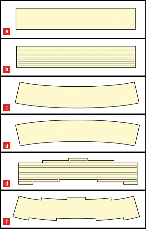
In the traditional approach of compensation (Figure 5), the complete part is subjected to a thermomechanical FEM simulation in each iteration step. The resulting new geometry is passed through the slicer again. With curved surfaces due to warpage, the slicing may lead to unexpected results, such as the emergence of the well-known staircase effect in designs that should not suffer from this phenomenon (Scheme 1).

Figure 5: Traditional shrink-compensation approach in the printing procedure.

Scheme 1. Staircase effect emerging from the traditional shrink-compensation approach.
a) Design
b) Sliced model
c) Originaldesignaftershrink
d) Design compensated for shrink
e) Sliced model of shrink-compensated design.
f) Printed part
Bond3D has developed, in collaboration with simulation specialists AniForm Engineering, a new, advanced shrink- compensation approach (Figure 6). This incorporates the dynamics of the printing process in the simulations, while at the same time minimising the computational effort.

Figure 6: Bond3D’s shrink-compensation approach incorporated into the standard printing procedure.
The compensation procedure is iterative, because the first modification usually will not provide full compensation. Therefore, a new simulation is performed until the feedback loop converges to a stable input geometry that produces the desired output geometry after shrink.
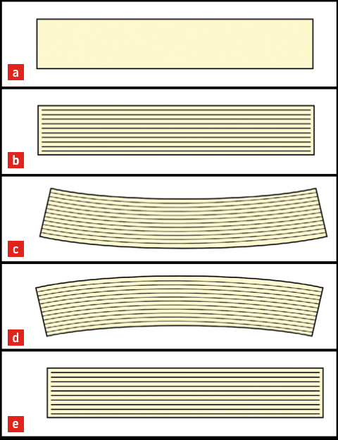
In Bond3D’s approach, the slicing is no longer included in the optimisation loop. The toolpaths as initially defined by the slicer are preserved, but they do move along with the shape modifications in the procedure: the strict printing of horizontal layers is abandoned and the height of each line can also be varied. As a result, no staircase effect will be created (Scheme 2).

Schema 2: Smooth part, without staircase effect, emerging from Bond3d’s shrink-compensation approach.
a) Design
b) Sliced model
c) Slicedmodelaftershrink
d) Shrink-compensated sliced model (e) Printed part
Results
Results
Bond3D has validated its new approach; compared to inter- national standards (Figure 7), the obtained dimensional accuracy is good. Figure 8 provides an illustration of the outcome of shrink compensation, showing the original shape, the shape of the part printed ‘as is’ and the shrink- compensated shape that will yield the desired shape. Excellent results have been obtained with functional parts. Figure 9 shows a printed test part; unfortunately, customer parts cannot be shown due to NDAs.

Figure 7: Length accuracy achieved by Bond3D’s shrink compensation, as compared to the ISO 2768 standard for manufacturing tolerances – coarse (c) and medium (m) – and the DIN 16742 Plastic moulded part tolerances for position tolerances.

Figure 8: Illustration of the outcome of Bond3D’s shrink-compensation procedure.
a) Desired shape to be printed.
b) Actual shape after printing without shrink compensation.
c) Compensatedshapethatissenttotheprinter,yieldingthedesiredshape.

Figure 9: The printed part on the left demonstrates that shrink compensation prevents deformations such as curved surfaces (right).
Outlook
Outlook
Bond3D is now in the final stages of implementing a further improvement of its shrink-compensation approach and incorporating this in its standard printing procedure. This is especially essential for large parts, in order to achieve dimensional accuracy. For small parts, compensation
is useful if the improvements are larger than the actual printing tolerances.
One of the factors that determine shrink, and the need
for compensation, is the crystallinity of the PEEK material. In collaboration with the University of Exeter (UK), Bond3D is conducting further investigations into (re-)crystallisation during shrink and the effect that the degree of crystallinity after printing has on dimensional accuracy and mechanical properties such as strength. There is no time yet to shrink down the research efforts.

