Designs by a
talented precision engineer
Designs by a talented precision engineer
Playing with friction
As a precision engineer, HenkJan van der Pol likes to apply the well-known design principles of Wim van der Hoek and Rien Koster
As a precision engineer, HenkJan van der Pol likes to apply the well-known design principles of Wim van der Hoek and Rien Koster. One interesting construction phenomenon in designs that have been created under his leadership is friction: sometimes useful, often avoidable. It is found for example, in a simple and precise actuator that works according to the friction-based stick-slip principle. Or in a print head – suspended friction-free from leafsprings – fitted with sensitive force sensors for pressure-controlled 3D printing.
Friction has a bad reputation in mechanical engineering. It is often undesirable due to wear, while in other cases it is lower than necessary for a particular application. Also, friction in a system produces parasitic damping that is difficult or impossible to compensate in the control. As soon as friction occurs when positioning an object, the position of that object is not immediately known. Friction can, however, also be applied usefully.
At the end of 2005, HenkJan van der Pol, then working at Demcon, received the Ir. A. Davidson Award for young precision engineering talent. Around that time, he was leading a design project that befitted his stature as an award-winning precision engineer and in which friction played a key role. It concerned a linear actuator, simple and cheap to produce, that could achieve a high accuracy and sub-micron resolution with the aid of feedback, while having a relatively large stroke. The actuator only exerted a small force, but that was no problem for accurate positioning of optical components, for example, or for use in a terminal for Braille communication (each Braille dot was a pin with such an actuator).
Stick slip
Of all the actuation principles for positioning and displacement, the piezo effect is perhaps the most suitable for electronic control and integration in a semiconductor environment – which is why it is popular in high-tech applications. Its disadvantage is the limited stroke in relation to the size of a piezo element. Combining the piezo effect with the so-called stick-slip effect results in an actuator principle with an essentially unlimited stroke.
The sawtooth movement of the clamped piezo and the resulting progressive movement of the pin.
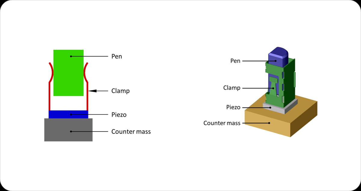
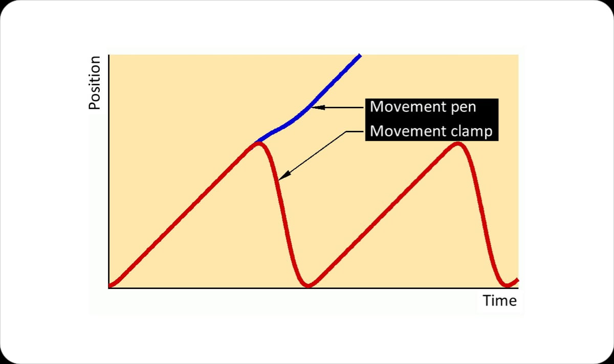
A piezo element, connected to the solid world, acts as a linear actuator and transmits a displacement to a clamp. During a movement with a small acceleration, the clamp can, due to friction, hold a pin (stick) and this pin is therefore imposed with the same displacement. With a large acceleration, the pin slips within the clamp due to its mass inertia and the displacement of the pin is almost zero (slip). Now let the actuator periodically move in one direction with a low acceleration (and thus take the pin with it because of the stick) and then move it in the reverse direction with a high acceleration (and not take the pin back because of slip), according to a kind of sawtooth. Then the pin will undergo successive movements in one direction. The sawtooth control is translated into a rectified movement. The result is a macroscopic displacement caused by an actuator with a microscopic range.
Forces
The stick-slip principle follows from a consideration of the forces. The clamp makes contact with the pin at a number of points and there exerts a clamping force (normal force) on the pin in the horizontal direction. This normal force can cause a frictional force in the vertical direction between clamp and pin. If the actuator moves the clamp with a certain acceleration (assuming upward), the pin will initially not want to follow this movement because of its inertia. There are two options here:
Important here is the non-linear nature of friction, as characterized by the well-known Stribeck curve. If two rubbing surfaces start to move relative to each other, the coefficient of friction decreases, starting from the static situation, with the relative speed, only to increase again at even higher speeds. Due to this behavior, when the clamp moves backward (if the speed is high, but the acceleration changes sign and is therefore briefly zero), the frictional force will be too low to ‘take the pin back.’
Sawtooth
The linear piezo actuator is electrically driven with an electrical signal that approximates a sawtooth. The position of the actuator follows this sawtooth, so that the upward movement is continued with a low acceleration (to even zero with uniform movement), and the downward movement is completed with a much higher acceleration. In this way, the pin is driven upward, after which it slips as the clamp moves downward. Repeating this cycle often results in a large displacement of the pen relative to the solid world. Due to the inertia of the pin, the sawtooth of the clamp is converted into a nearly constant speed of the pin. In order for the pin to move in the reverse direction (‘return’), the sawtooth signal must be reversed (i.e. quickly up and slowly down).
Origami
The implementation chosen for the clamp resembles an origami model, punched from plate and then folded. This procedure lends itself to serial production. The pen is made of tungsten and two sides have been ground flat. The spring fingers of the clamp grasp those surfaces, while the two closed side surfaces of the clamp make minimal contact with the curved pin surface. This construction, statically well determined, ensures that the normal forces are easily predictable. The well-predicted normal force in combination with the conformal geometry ensures a low Hertz contact pressure, preventing wear despite the friction.
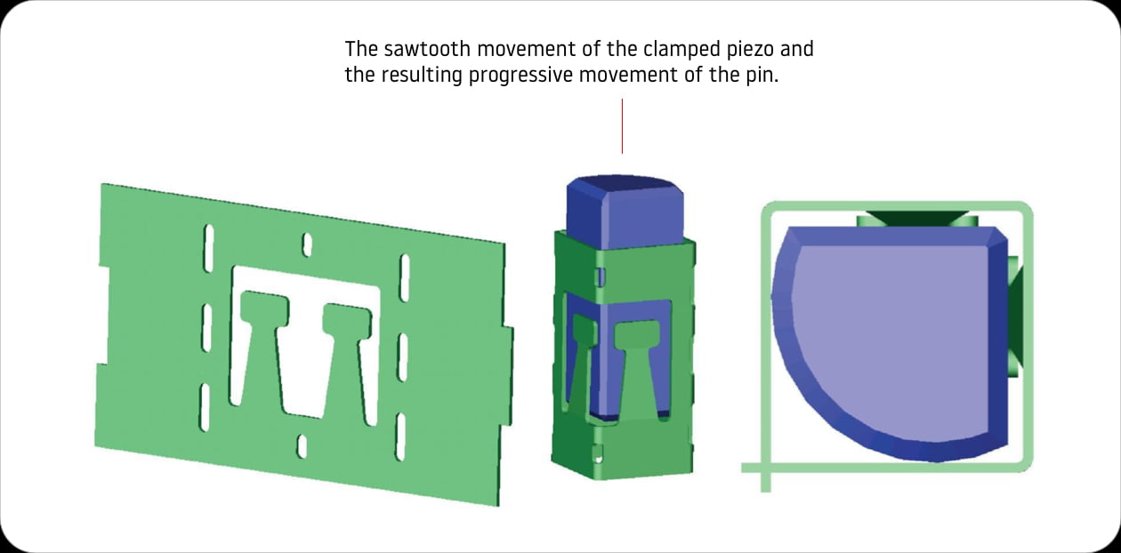
The clamp as an origami model: on the left the result, on the right the folded version with pen (in side and top view).
Strong and voidless
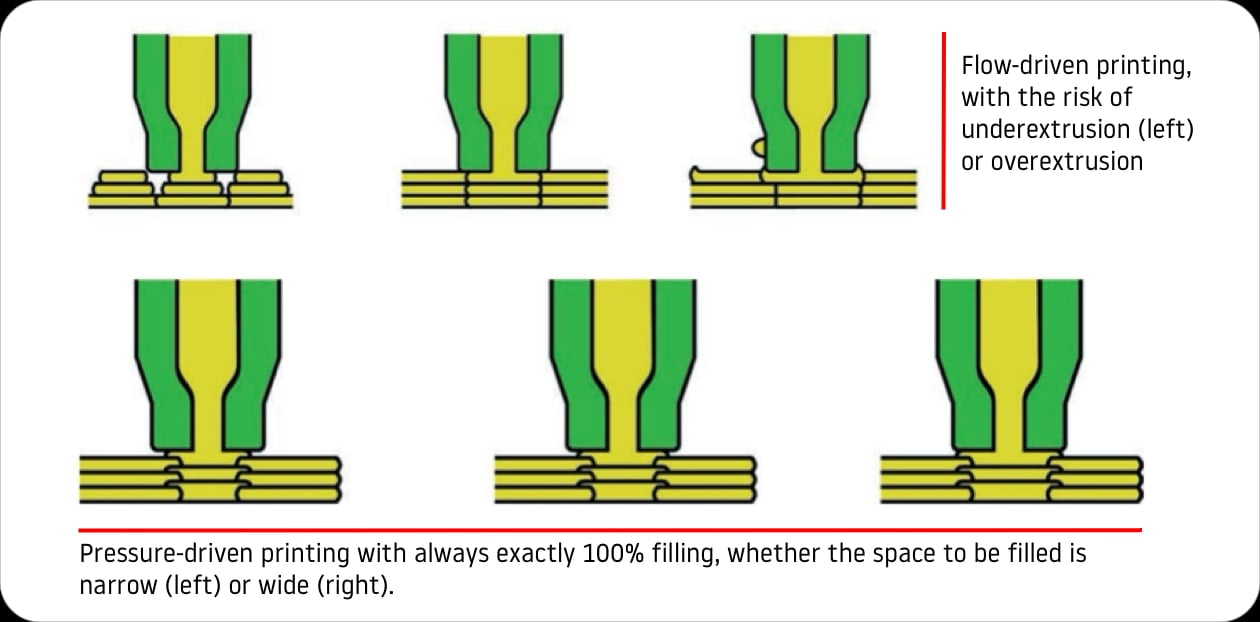
Friction is often completely undesirable, for example because of its disruptive influence on the accuracy of positioning or (force) measurement. The latter plays a role in the design of a print head for pressure-driven 3D printing in which Van der Pol has been involved, first as business unit manager at Demcon and later as technical director at Bond3D. A commonly used printing technique such as fused deposition modeling is flow-driven. With a constant flow, tracks are deposited layer-wise by extruding heated material from the print head. The risk is that the tracks do not connect completely (underextrusion) or that too much material is printed (overextrusion). Voids can form in the product and this effect is enhanced by the fact that tracks in successive layers are often printed crosswise (in the x- and y-directions). Subsequently, those layers in the z-direction (the direction in which the product is built up layer by layer) often do not fully connect to each other. The printed product therefore has a lower tensile strength in that direction and is thus anisotropic in its material properties.
Pressure-driven printing
Bond3D’s printing process also works in layers, but is pressure-controlled. The print head has a built-in pressure-sensing mechanism to determine when the space below the nozzle has been filled. After the contours (‘flow lines’) of the desired product in a layer have first been printed in a flow-controlled manner, the space between those tracks is then filled exactly 100% in the pressure-controlled manner (there is a small gap between the print head and the flow lines to prevent mutual parasitic forces). So, no voids are created and the material properties are the same in all directions, comparable to the bulk properties. The process delivers products that are isotropic and voidless. This makes them strong and suitable for machining-type finishing in the case of a high-performance thermoplastic polymer such as PEEK (poly ether ether ketone), for which Bond3D developed its printer. PEEK is used, among other things, to replace metal components when lightweight is a requirement.
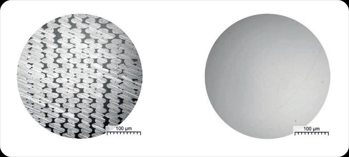
Cross-sections of a product that has been printed either flow-controlled (left) or pressure-controlled (right).
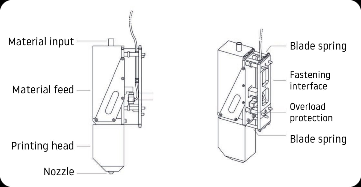
Schematic design of the ‘loose’ print-head suspension with leafsprings. The ball support prevents the print head from sagging as long as the weld pool does not exert sufficient force on the print-head nozzle.
Friction-free suspension
The pressure can be derived from the buoyant force exerted by the printed material in the weld pool below the print head on the nozzle at the bottom of that head. Initially, the idea is to derive this force from the motor current needed to drive the extruder that feeds the print material into the nozzle. This motor current is a measure of the pressure in the nozzle, but gives a rather noisy signal. In addition to this indirect form of force measurement, which requires high-bandwidth control, Bond3D has opted for direct measurement of the pressure below the nozzle with sensitive force sensors (load cells) attached to the print head. The print head in turn is connected to the XY stage, which allows the head to move according to the desired print patterns. Measuring the force in the vertical direction requires that the print head is disconnected from the ‘fixed world’ in that direction. To this end, the head is suspended ‘loosely’ with leafsprings, free from hysteresis and friction – resulting in an undisturbed measurement. The motor current is now used for precise extrusion of the flow lines, while the load cell signal is used for pressure-controlled printing. This combined control improves the dimensional accuracy of printed parts.

